Electrical Circuit Analysis
Contents
Electrical Circuit Analysis
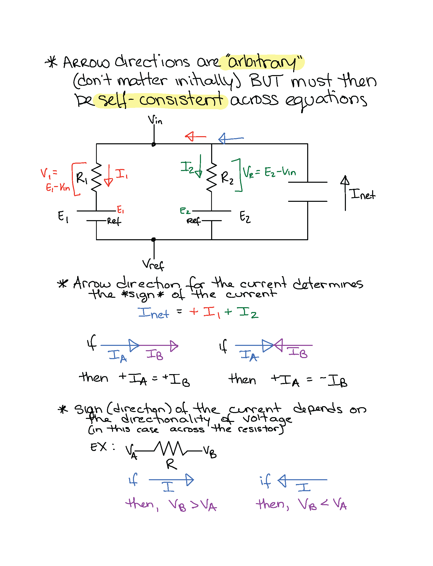
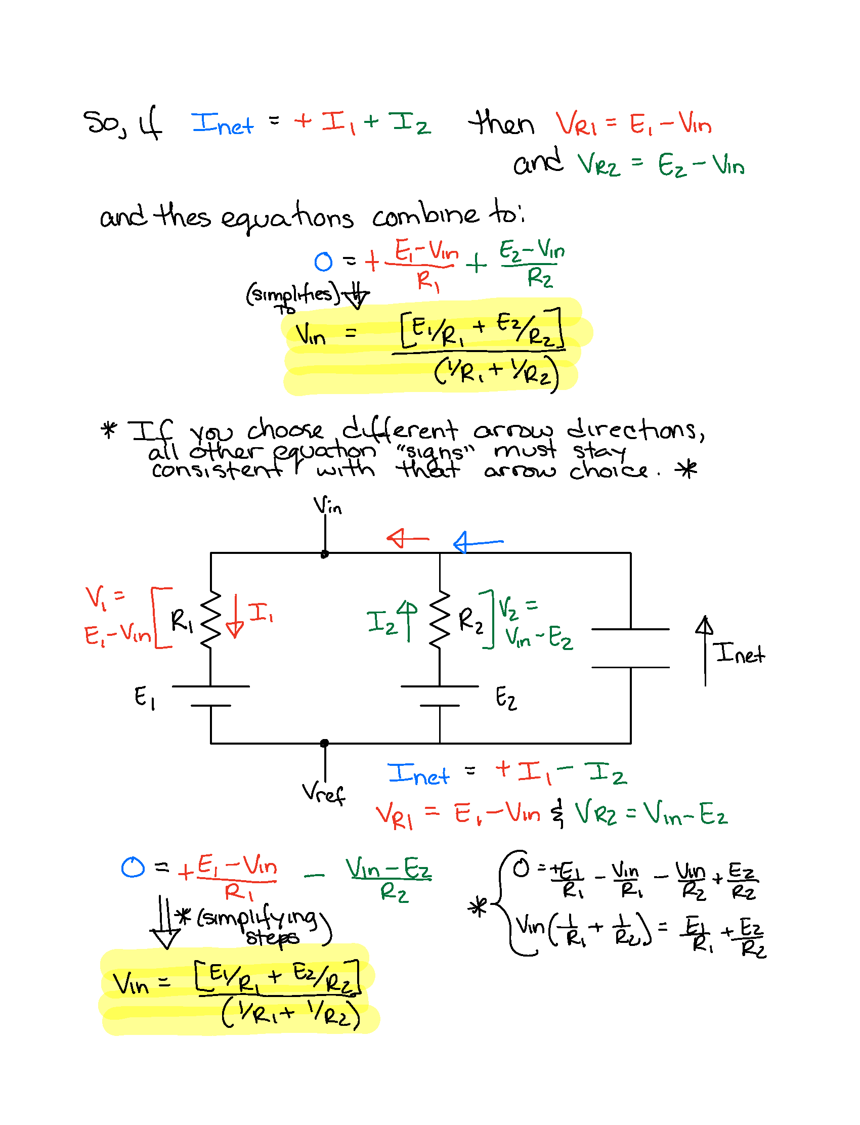
Conservation of Charge
An example of circuit analysis implementing the law of conservation of charge. This example is from the Passive Membrane Potential computational model.
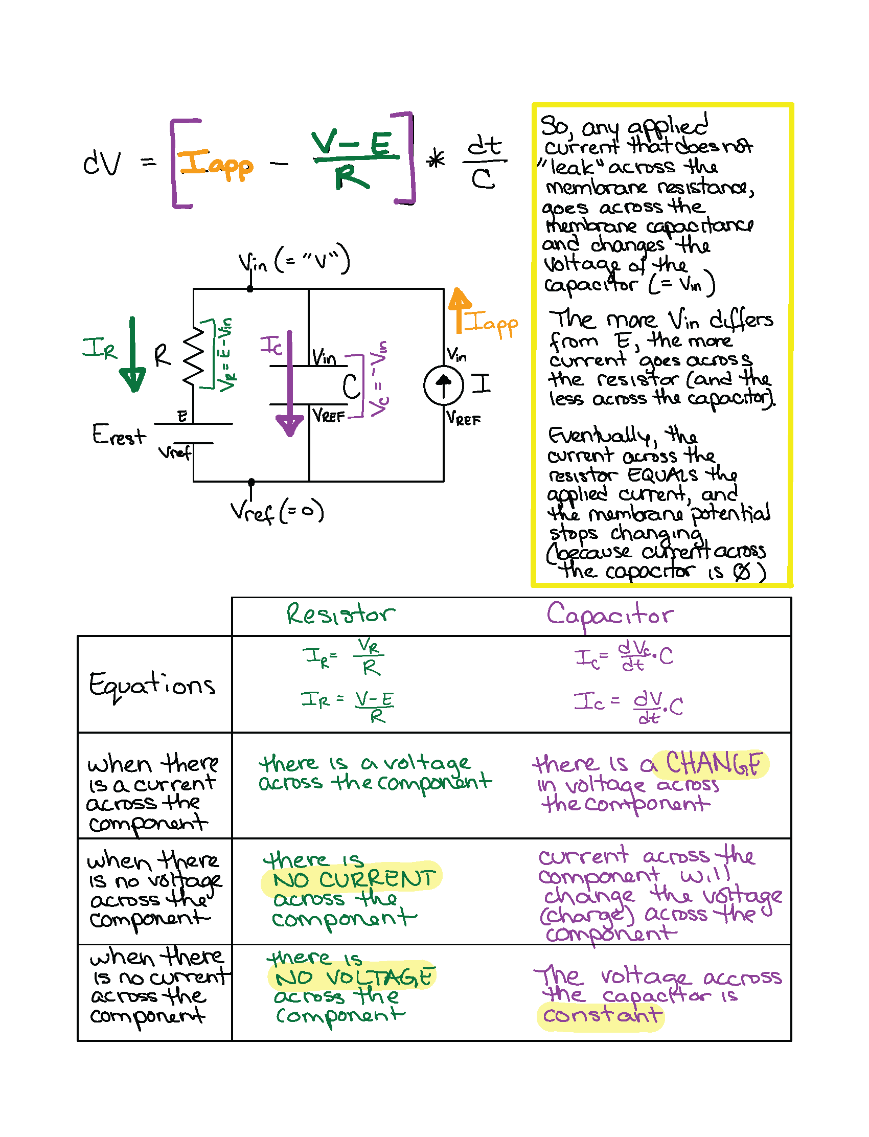
Applied current across RC Circuits
By the law of conservation of charge, we find the following equation that predicts the membrane potential value in resopnse to applied current:
Implications for understanding membrane potential responses
The change in membrane potential in response to an applied current does not reach it’s expected Ohmic value (according to V = IR) immediately. Instead, current preferentially flows across the capacitor (which has effectively no resistance). However, the full applied current cannot keep flowing across the capacitor because, once there is a voltage across the resistor, the resistor draws current across it. As the voltage across the resistor increases, more current must flow across it (and therefore less current is availble to charge the capcitor).