Lab Manual
Contents
Lab Manual
You will record extracellularly from nerve 2 while curling the tail to stimulate MRO proprioceptors. This recording will allow you to determine the stimulus-response tuning curve (sensory coding) of the MROs and various dynamic properties of the MRO neural code.
If there is time, you can also use this preparation to better understand how common anaesthetics work (for example MS222 or ice).
Hardware Setup
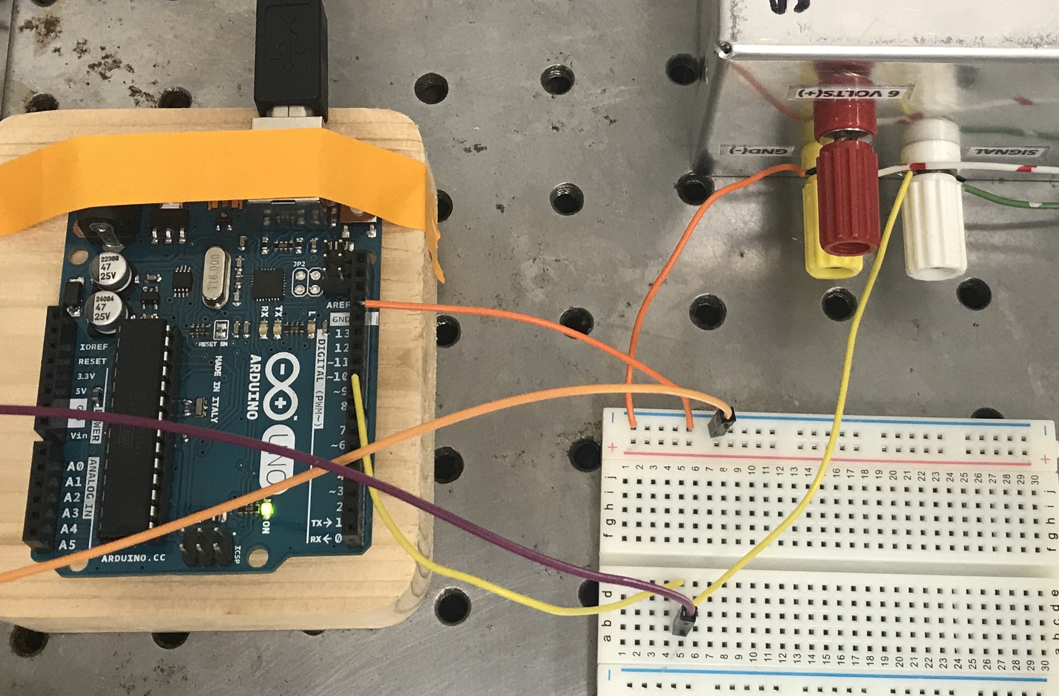
Fig. 20 Servo motor control and stimulus monitor circuit. The 6V battery pack (upper right) powers the servo motor. The battery ground (negative lead) must be tied to the Arduino ground (GND) and the NIdaq AISN. Arduino Pin9 (PWM digital output) provides the signal to the servo motor and is also sent to a NIdaq AI NRSE.
Software Setup
The bonsai script for today has one measurement node. Channel 01 receives amplified and digitized input from the measurement electrode relative to the ground electrode. Channel 12 receives input from a floating voltage source (the Pulse-Width Modulated (PWM) signal from the Arduino Digital Output pin.
Use a sampling rate of 30kHz. Adjust the voltage range for each channel in the AnalogInput parameters if needed to maximize the signal resolution if needed based on your MRO nerve recordings (options include: ±0.2 V, ±1 V, ±5 V, ±10 V). The PWM signal is a 5V signal so the range should be ±5 V for that channel. Adjust the buffering samples according to your visualization preferences.
Make sure that the Ardiuno COM port is correct in the CreateArduino and ServoOutput nodes.
Surgery
For this lab, you will be removing the tail from a crayfish. A major benefit of targetting the MRO for measurement is that crude surgical techniques work better than fine surgincal techniques.
You can refer to this video from JOVE3 for an example demo of the surgery.
Tip
The surgery in the video is overall a good example, but there are a few notes that I would recommend doing differently.
I prefer to cut along the ventral edge of the abdominal carapace instead of the dorsal edge as in the video because there is less risk of cutting the nerves. Cut between the swimmerettes and the edge of the carapace.
The tissue health will likely be better if you are able to use a small finger to push the muscle away rather than a forcepts edge. You will have a better sense of the pressure you are using and where you are touching.
The decerebration step shown in the video is to kill the crayfish by brain damage.
From an anaesthetized crayfish, cut the tail from the abdomen (as close to the abdomen as possible).
Cut along the ventral edge of the carapace as close to the ventral side as possible.
Use your finger or the handle of a pair of blunt forcepts to push the fast flexor muscle away from the dorsal surface. Take care not to push down too hard against the tissue left on the dorsal surface. Use scissors if necessary to cut the nerves away instead of pulling at them (though for many people this is less reliable than ripping them by pushing the muscle away).
Pin the anterior segment of the tail down on the dish (dorsal side down) using two pins. Take care not to crack the carapace apart. Pour saline into the dish until just below the carapace edge.
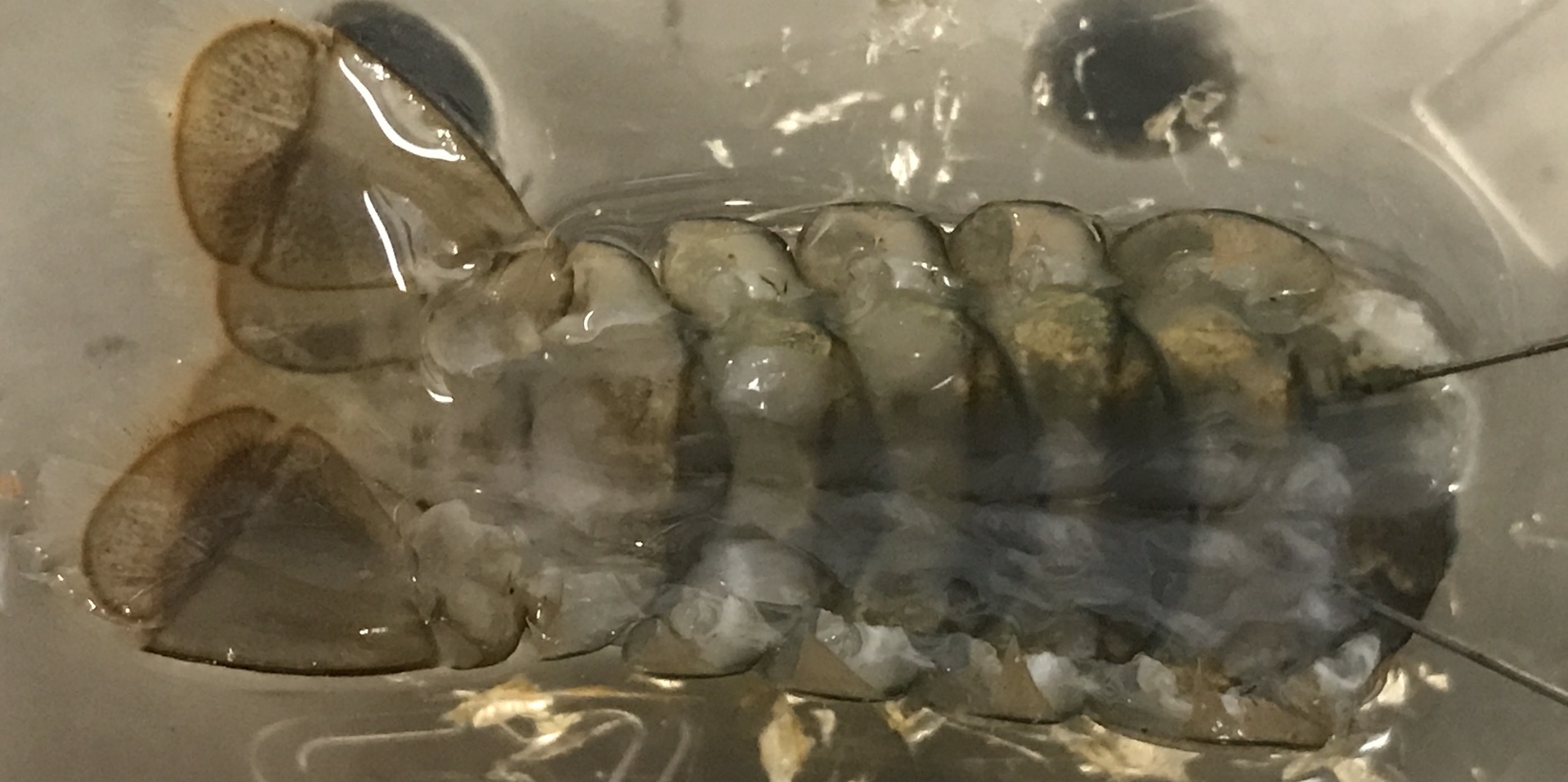
Fig. 21 Crayfish tail (cleared of overlying fast flexor muscle) pinned to the dish.
Thread a thread through the middle telson fin. Tie it gently but firmly. Trim the thread so that it does not interfere with the electrode. You will attach the free end of the thread to the servo motor horn after you test and calibrate the stimulation control.
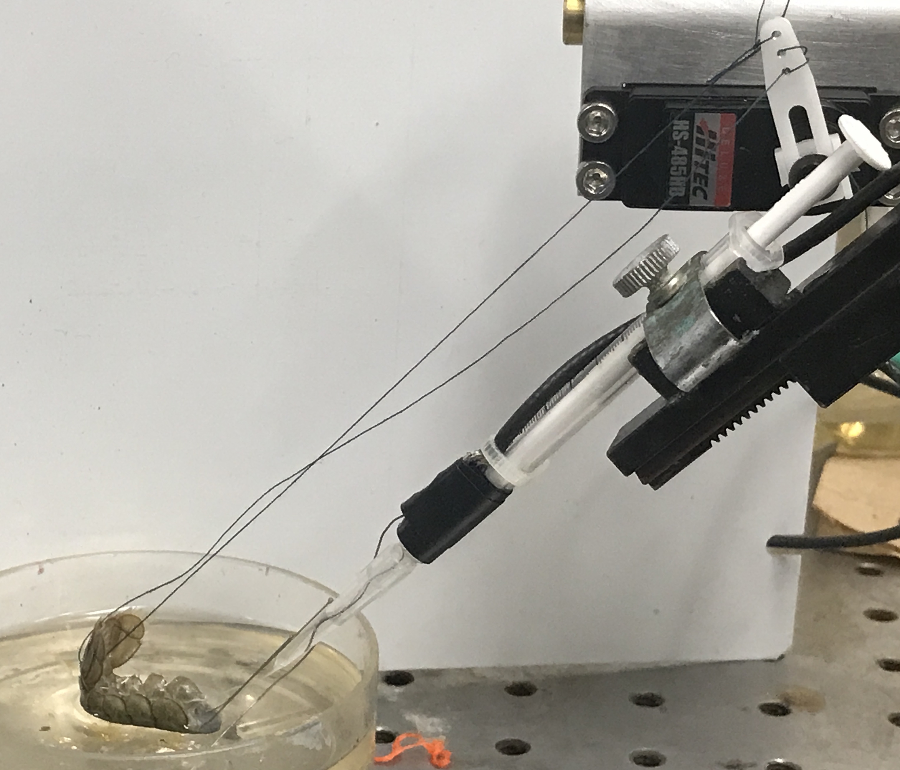
Fig. 22 Suction electrode placed near an N2 root. Thread attaching telson fan to the servo motor horn.
Physiology Setup
Identify the nerve roots (N2) near the base of the tale. You can refer to the figures below and this video from JOVE3 to help identify the nerve root. Select or make a suction electrode tip that has an inside diameter approxiamtely the diameter of the nerve. Connect the electrode to the amplifier input block: electrode inside suction tip goes to a differential input of the amplifier; electrode outside suction tip (in bath) goes to the other differential input (which is tied to amplifier reference/ground). Don’t suction the nerve into the tip until you have tested your stimulation setup and control.
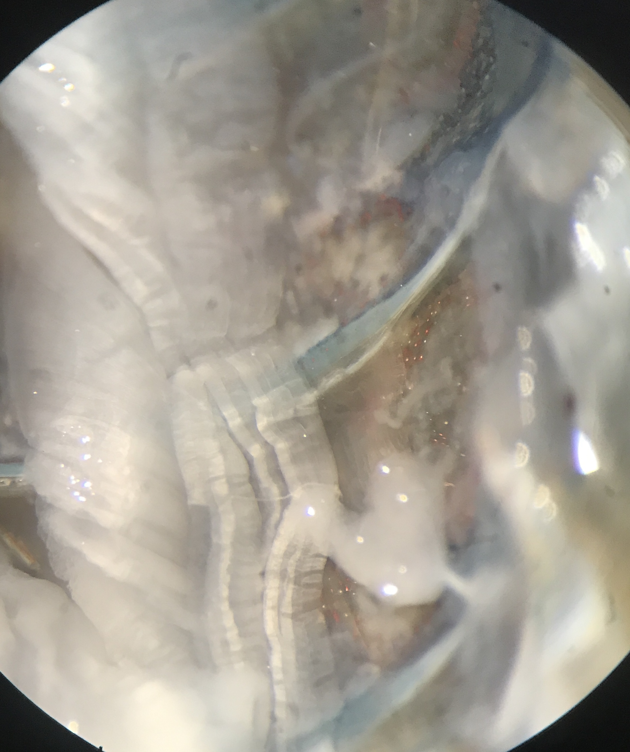
Fig. 23 Example N2 visualized through microscope.
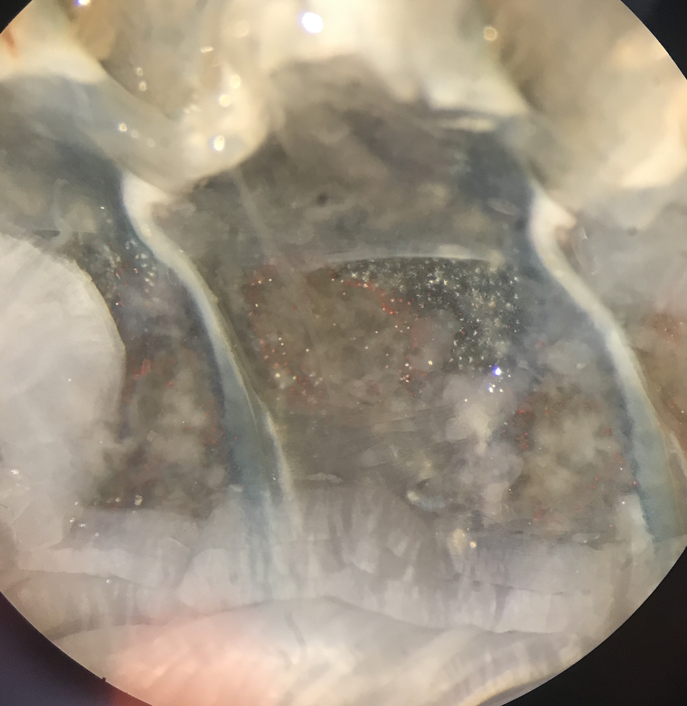
Fig. 24 Example N2 visualized through microscope.

Fig. 25 Example N2 visualized through microscope.
Core Experiment
General Bonsai modes
Visualize Analog Inputs
Run the bonsai protocol with the write node disabled and the analog input and channel select nodes enabled. Double click the channel select nodes to visualize the electrode and stimulus measurements if it does not pop up upon start.
Record Analog Inputs
Run the bonsai protocol with the write node enabled (and the analog input and/or channel select nodes enabled). Change the filename as needed.
Stimulation Control
You will use a servo motor to pull the thread attached to the tip of the tail. The goal is to bend the tail to varying degrees and examine how the MRO encodes stretch. By controlling the position command to the servo motor with the movement of your computer mouse, you will be able to deliver a relatively quantifiable and controlled stimulus that can be synced with the recording of MRO neural activity.
Practice the stimulation before trying for the MRO nerve recording. You will need to adjust the range on the control command to bend the tail across its full range, which will depend on tail size and servo motor positioning, etc.
Before you start testing your stimulus, make sure that the tail thread is not attached to the servo motor.
Mouse control
Disable all nodes except for the MouseMove, X, and Rescale nodes.
Run the Bonsai workflow and visualize the X, and Rescale nodes.
Move your computer mouse horizontally across the full range of the monitor. Note the min and max values of X for the mouse (depends on the monitor).
For now, the min and max properties of the Rescale node should match your computer mouse’s min and max X range. You can adjust this range to get finer control over the relevant servo motor rotation range once you have MRO responses.
Stop the Bonsai workflow.
Servo command
Enable all other nodes except the Matrix Writer and move the Bonsai editor window on the screen so that the Start button is all the way to the left of your screen.
Run the Bonsai workflow.
Visualize the stimulus monitor channel (ch 1) and the Detect Spikes node for that channel. Get familiar with what this signal looks like. Notice how the width of the square pulses change as you move your mouse left <-> right on the computer screen.
Stop the Bonsai workflow.
Tune the stimulus range based on MRO activity
Tie the free end of the thread through the tail fins.
Run the Bonsai workflow and keep the computer mouse hovered over the start button after you press it.
Move your computer mouse slowly across your screen to the right. The servo motor should be rotating. Continue moving it until the servo motor horn is in a good position to start the tail pull. Note the X position.
Change the Range min of the Rescale node to match the X position from step 3.
Move your computer mouse slowly across your screen to the right until the tail is maximally bent but not more than that. Note the X position of the mouse.
Change the Range max of the Rescale node to match the X position from step 5.
Stop and restart the Bonsai workflow and check that the full range of tail motion is captured well by the full range of the mouse movement in the X direction.
Stop the Bonsai workflow and go on to set up the MRO nerve measurement.
Warning
Do not move the location of the bonsai workflow window. The start button position needs to be in the same place each time you start the workflow so that the servo motor starts in the same position.
MRO nerve measurement
Make sure that your audio monitor is turned on. This will help you interpret the MRO response.
Find the MRO nerve. Aim for one in the anterior segments. The nerve is white, and can be seen by using the pipette to spray saline around the nerve. This causes the nerve to move around and makes it easier to identify.
Place the suction electrode from the micromanipulator directly over the nerve tip.
Gently pull on the syringe to draw the nerve into the electrode (look through the microscope while you do this to see the nerve being sucked into the electrode). Move the manipulator as needed to suck more of the nerve up without stretching it.
Manually pull on the string gently as you watch through the microscope to keep track of the nerve in the electrode tip. Listen and look for action potentials as you stretch the MRO in the section of the tail you are recording from.
Start the Bonsai workflow and keep the computer mouse hovered over the start button after you press it.
Make sure that the baseline electrical noise levels are low. If not, we will need to work on de-noising (grounding, laptops and cell phones away, metal wire mesh coverings, etc).
Move your computer mouse slowly across your screen to the right until the tergite of your targetted MRO nerve rotates around its joint (the joint bends… and the MRO muscle stretches). You should be able to see (and hear) spikes from the MRO nerve. If not, check the suction electrode placement, nerve identity, and nerve fit in the electrode, etc. You may need to straighten the tail again to fix or optimize the MRO nerve recording.
Once you have MRO spikes, SLOWLY continue rotating the servo motor further to bend the tail more. Make sure that the suction electrode is not jamming into the tail or the nerve. Make sure that the nerve is not falling out of the suction electrode when the tail bends. You should observe an increase in MRO nerve spike rate as the tail bends more. Be gentle with the tail and nerve and keep the stimulus within a reasonable physiological range.
Move your mouse slowly back to the starting position and stop the Bonsai workflow.
You are now ready to do the main experiment.
Main Experiment: Progressive Steps
Run the bonsai protocol (with the MatrixWriter node disabled and the AnalogInput node enabled). Double click the analog input node to visualize the measurement if it does not pop up upon start.
Set up the following ‘progressive step’ stimulation protocol in which you will bend the tail different amounts from the same position:
Rotate the servo motor (using horizontal mouse movement) until the MRO nerve starts spiking. Mark this mouse position with washi tape on the computer monitor.
Rotate the servo motor until the maximum bend that you feel comfortable with. Mark this mouse position with washi tape on the computer monitor.
Return the servo motor position to the start.
Make three evenly spaced washi tape markers between the tail start and stop position on the monitor. You should now have one tape marker for the start position and a tape marker for each of four evenly spaced target positions.
Stop the Bonsai protocol.
Enable the MatrixWriter node. Specify a filename that will make sense to you later (make sure the filename ends in ‘.bin’).
Start the Bonsai workflow.
Execute the ‘progressive step’ stimulation protocol.
When moving the mouse to different locations, try to be consistent about the speed of your movement. Move swiftly but with control.
Start with the computer mouse at the start tape position that you marked.
Move the mouse to the first target tape position and hold it there for 10 seconds.
Return the mouse back to the start position and hold it there for 10 seconds.
Repeat the movement to the first target position and back to the start a total of 3 times.
Repeat steps 2-4 for all target positions.
Stop the Bonsai protocol and make sure that the file saved where you think it did (and is not empty).
You should now have raw data that will let you ask questions about MRO spike rate encoding of stretch amplitude across 4 different stretch conditions.
Experimental Exploration
Choose one of the following (or an idea of your own) to test:
slow versus fast stretch
same change in stretch, but starting from different initial positions
The following would need some modification to the Data Explorer analysis already provided, so let me know if you want to do one of these and I will make that modification.
effect of duration of stretch on offset dynamics when tail is relaxed.
is the onset and offset spiking dynamics the same? (Need to start from a stretch that drives a non-zero baseline spike rate)
Housekeeping
Clean up your area.
Copy data to an external drive or your Google Drive for later.
Use the Data Explorer notebook to process and analyse your raw data. Answer the questions in the Responses notebook. The Dash DataExplorer.py application is available to explore your raw data in detail.